

High-performance industrial camera

I. Classification of Industrial Cameras
There are many types of industrial cameras. Figure 1 shows the classification of industrial cameras based on several different classification criteria.

图1 工业相机的分类
According to the different types of camera sensors, they can be divided into two categories: CCD (Charged Coupled Device) and CMOS (Complementary Metal-Oxide Semiconductor).
A CCD sensor is a silicon chip containing numerous light-sensitive areas, as shown in the figure. The working principle of a CCD is to convert optical signals into electrical signals, which are then transmitted in sequence to a common output structure. The charge is then converted into voltage, and these signals are sent to a buffer and stored outside the chip, as illustrated in Figure 2.

Figure 2 Schematic Diagram of CCD Structure
In a CMOS sensor, the charge on the photosensitive pixels is converted into voltage within the pixel area. The signals are multiplexed by row and column and fed into the on-chip Digital-to-Analog Converter (DAC). Each area consists of a photodiode and three transistors, which perform the functions of pixel reset or activation, charge amplification and conversion, and selection or multiplexing, as shown in Figure 3.

Figure 3 Schematic Diagram of CMOS Structure
CCD and CMOS each have their own advantages in different application scenarios, as shown in Table 1.
|
Table 1 Comparison of CCD and CMOS Sensors
CCD has advantages such as high signal-to-noise ratio, strong transparency, and excellent color reproduction. It is widely used in high-end fields such as screen inspection, transportation, and medical care. However, the high cost and high power consumption of CCD have restricted the room for its market development. With the continuous improvement of CMOS technology and the decreasing price of high-end CMOS, CMOS will occupy an increasingly important position in the field of machine vision.
A shutter is a mechanical device used to control the exposure time of a photosensitive element or film. To protect the photosensitive element or film in the camera from overexposure, the shutter is always closed. After setting the shutter speed, once the camera's shutter release button is pressed, the light passing through the lens will properly expose the photosensitive element or film during the time the shutter is open.

Figure 4 Principle of Global Shutter
A rolling shutter means that when the chip starts exposure, each row begins exposure sequentially in order. After the first row finishes exposure, it immediately starts reading out data; once the data is completely read, the next row begins to read out data, and this cycle continues. Pixels in different rows have different start and end times for exposure, as shown in Figure 5.
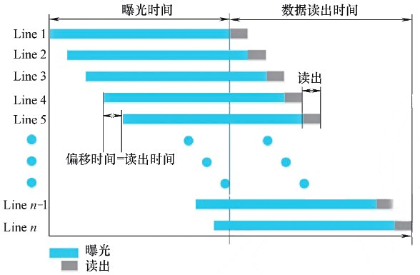
Figure 5 Principle of Rolling Shutter
When shooting moving objects, there are significant differences in the effects between global shutters and rolling shutters. If exposure is done using the global shutter method, all pixels are exposed within the same time period, which can "freeze" the object in the shot. In contrast, with the rolling shutter exposure method, since the start and end times of exposure for pixels in different rows vary, image distortion such as bending may occur. Therefore, rolling shutter cameras are usually applied in static or low-speed scenarios, while global shutters are typically used in dynamic situations, such as high-speed flying shots.
The data interface of an industrial camera refers to the interface through which the camera transmits data to a computer after image acquisition, with each interface following specific communication protocols. According to the type of data interface, it can be divided into various types of data transmission interfaces such as Gigabit Ethernet (GigE), 10 Gigabit Ethernet (10GigE), USB 3.0, Camera Link, and CoaXPress. Different data interfaces have different characteristics, and users can choose based on comparisons in aspects such as cable length, transmission speed, latency, and cost.
| Interface | Gigabit | 10 Gigabit | USB 3.0 | CameraLink | CoaXPress |
| Speed/(Gbit/s) | 0.1 | 1 | 0.3 | 0.64 | 2.56(4根) |
| Distance/m |
>100 (Fiber Optic) |
>100 (Fiber Optic) |
5(Standard Passive Cable) >5(Fiber Optic) |
10 |
45(CXP-6) 35(CXP-12) |
| Cost | Low | Middle | Low | High | High |
| Advantages |
|
||||
| Disadvantages |
|
Table 2 Comparison of Data Interfaces
II. Performance Parameters of Industrial Cameras
Industrial cameras have many parameters, and customers can choose appropriate parameters according to their actual usage needs. The following will introduce the important performance parameters of the camera.
1、Resolution
2、Pixel Size
The pixel size refers to the actual physical size of each pixel on the pixel array of the chip. When the target size is the same, the smaller the pixel size, the higher the resolution.
3、Target size
The target size refers to the photosensitive area of the camera's image sensor, which is generally identified by the length of the diagonal, with the unit being in (inches). Under normal circumstances, when other conditions such as pixel size are fixed, the larger the target size, the higher the resolution of the camera.
4、Frame Rate/Line Frequency
5、Pixel Depth
Pixel bit depth (also known as pixel depth, image depth, or grayscale) refers to the number of bits used to store a single pixel. It determines the possible grayscale levels for each pixel in a grayscale image or the possible number of colors for each pixel in a color image. A higher bit count allows for more detailed readout, but a higher bit depth can slow down the frame rate.
6、Exposure time
Exposure time (shutter time) refers to the duration during which the pixels are exposed to light. Under the same external conditions, the longer the exposure time, the higher the brightness of the image. However, an excessively long exposure time will reduce the frame rate/line rate. Different cameras have different upper and lower limits of exposure. In some flying shot applications, insufficiently short exposure will cause image smearing, so industrial cameras need to have the capability of imaging within an extremely short exposure time.
7、Signal-to-Noise Ratio, SNR
The signal-to-noise ratio (SNR) refers to the ratio of signal to noise in an image, with the unit being decibels (dB). The higher the signal-to-noise ratio of an image, the better the image quality.
8、Dynamic range
Dynamic range refers to the difference between the minimum detectable light signal and the maximum detectable light signal, reflecting the range of light signals that an industrial camera can detect. The larger the dynamic range, the more obvious the display of details in the bright and dark areas of the image.
9、Spectral Range
The spectral response characteristic refers to the ability of a chip to respond to light of different wavelength bands, which is usually characterized by a spectral response curve. When selecting an industrial camera, it is generally necessary to choose a chip according to the wavelength band of the light source in the actual application scenario to achieve the best imaging effect.