

Fiber Optic Collimator - Aspherical Mirror Series


1. Principle of optical fiber collimator
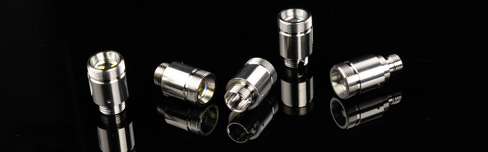
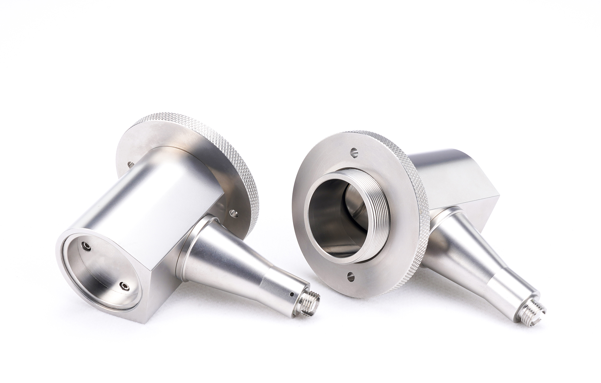
Fiber Collimator (FC) is a common passive optical device in fiber optic communication. Fiber optic collimators can either convert the fiber output beam into a free-space collimating beam (parallel beam) or couple a free-space parallel beam into a single-mode fiber. There are two different types of fiber collimators: the first is a collimator that is in direct contact with the exposed fiber, but this collimator is usually permanently attached to the fiber; The second category is collimators with mechanical cross-sections between the connector and the connector, such as FC/PC, FC/APC, SMA fiber optic splices, which can be easily installed or removed from the fiber of the connector.
2. Calculation of key parameters
Mode Field Diameter (MFD) generally refers to the maximum distance between the two points in each point of the e-squared point when the light intensity is reduced to 1 of the maximum light intensity at the axis line, which is used to represent the distribution state of the base mode light in the core region of the single-mode fiber. The light intensity of the base mold is the largest at the axis line in the core region, and gradually decreases with the increase of the distance away from the axial line.When using a fiber collimator to collimate the fiber output beam, the following parameters need to be considered: divergence angle, output beam diameter, and maximum beam waist distance.
1. Divergence Angle (expressed in terms of usage) can be approximated according to the following formula
where MFD is the diameter of the mold field and f is the focal length of the collimator.
This formula applies to single-mode fibers, but it will be less than the divergence angle of multimode fibers because the light emitted by multimode fibers has a non-Gaussian intensity distribution.
2. The Output Beam Diameter can be approximately calculated according to the following formula
where λ is the wavelength of the light used, f is the focal length of the collimator, and MFD is the diameter of the modulus field.
3. Maximum Waist Distance refers to the farthest distance from the lens to the lens due to the existence of divergence angle in actual transmission, in order to maintain the collimation of the output beam, the waist can be approximated according to the following formula
where f is the focal length of the collimator, λ is the wavelength of the light used, and MFD is the diameter of the modulus field.