

Aspheric Bare Lenses
一、Inspection index
Due to the existence of processing errors, etc., there will be deviations between the surface of the optical element and the ideal surface, thus affecting the imaging quality of the optical system. Surface shape error and parameter error are typical indicators describing surface shape deviation.
1、Surface shape error
Surface shape error refers to the point-by-point difference between the actual aspherical surface shape and the ideal aspherical surface shape, which is characterized by the peak and valley values (the difference between the peak and valley values of the deviation of the optically processed surface relative to the ideal reference surface at each point) and the root-mean-square value (the root-mean-square value of the deviation of the optically processed surface relative to the ideal reference surface at each point).
2、Parametric error
Parametric error refers to the existence of errors in the parameters of the aspherical expression, such as the conic constant k in the standard formula for aspherical lenses. therefore, the surface shape error and parametric error have a significant impact on the optical properties of aspherical surfaces.
二、Detection Method
According to whether to contact the measured surface, the main detection methods of aspheric surface shape can be divided into contact measurement method and non-contact measurement method.
1、Contact measurement method
First, the coordinates of the measured aspheric surface are measured point by point. Secondly, surface fitting is performed on the measurement results to obtain the measured values of vertex radius of curvature and quadratic surface constant. Finally, the difference between the nominal value and the measured value is calculated, i.e. the aspheric surface parameter error; the point-to-point subtraction of the fitted surface and the measured surface is used to obtain the random deviation distribution, i.e. the aspheric surface shape error.
2、Non-contact measurement method
Non-contact measurement method of measurement accuracy is relatively high compared to the contact measurement method, will not cause damage to the measured surface, but the measurement is more difficult. Non-contact measurement method is divided into two categories: geometric detection method and interference detection method.
(1)Geometric detection method
Mainly includes the knife edge detection method, Ranch detection method, Hartmann wavefront detection method.
① Knife-edge detection method
Knife-edge detection detection lens principle , the principle is based on the deformation of the measured surface makes the light deviate from the original trajectory, by blocking these deviating light to determine the lateral displacement of the light.
②Lange detection method
The principle of the Ranch detection method is shown in Figure 1, which is based on the principle that when a low-frequency grating is placed in the center of curvature of the aspheric mirror under test, the image of the grating falls back to the grating and produces Moore's fringes, and the shape of these fringes carries the information of the face shape error of the mirror under test.
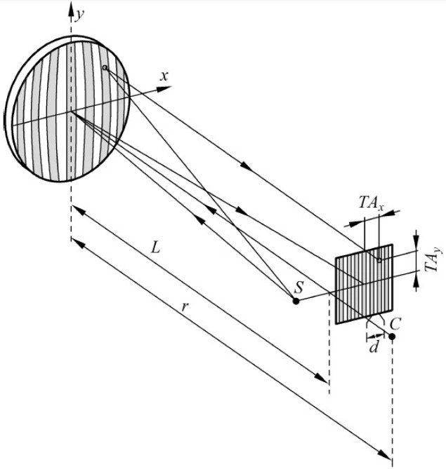
Fig. 1 Schematic diagram of the Ronchi detection method
③ Hartmann Wavefront Detection Method
The principle of the conventional Hartmann wavefront detection method . To measure the face shape, the light is sampled by the Hartmann diaphragm near the pupil surface, and the spot formed by the light is detected with a detector near the focal plane, and the slope matrix of the detected light is obtained from the position of the light on the Hartmann diaphragm and the detector surface to recover the face shape of the mirror under test.
Shack-Hartmann (SH) wavefront sensor is based on the classical Hartmann wavefront detection method, combined with microlens arrays, charge-coupled device (CCD) image acquisition, as well as the development of processing technology from the modern wave aberration sensing instrumentation can be used to detect the surface shape of the asphere with the SH wavefront sensor.
(2)Interference Detection
Interference detection method by the incident laser beam splitting, a beam reflected by the reference mirror, a beam reflected by the mirror to be measured, the two laser beams in the image surface interference. Through the distribution of light intensity in the interferogram, the distribution of wavefront on the image plane can be deduced, thus obtaining the face shape error of the measured surface. According to the relationship between the measured wavefront and the measured surface, the interference detection method can be divided into two categories: zero-position interference detection method and non-zero-position interference detection method.
1、The zero position interference detection method
Zero interferometric detection method with the aid of the compensator as an auxiliary optical element, the plane wave or spherical wave is converted to the theoretical shape of the surface to be measured with the same wave front, that is, through the compensator to fully compensate for the measured surface of the normal aberration. At this time, the normal of the wave front emitted from the compensator coincides with the normal of the theoretical measured surface everywhere, so that the wave front aberration measured by the interferometer system is completely caused by the surface shape error of the measured surface, and high precision measurement of the measured surface can be realized.
Zero interferometric detection method can be divided into process surface detection method, no aberration detection method, zero compensation method, computational holography method and adaptive zero interferometric detection method. This paper mainly introduces the zero compensation method, calculated holography and adaptive zero interference detection method.
(1)Zero compensation method
The schematic diagram of the zero-position compensation method, the detection beam is emitted from the interferometer to the compensator, and the beam is reflected in the measured aspherical surface through the compensator, and then returned to the interferometer through the compensator. At this time, the detection light containing the measured aspheric surface shape error information and the reference light interferes with each other to form interference fringes, which can be analyzed and processed to obtain the surface shape error of the aspheric surface.
(2)Computational holography
The computational holography method utilizes computers, plotters and photographic techniques to synthesize holograms. To detect the aspherical surface by this method, it is first necessary to utilize the above equipment and related processes to make a corresponding computational hologram (CGH) with the measured aspherical surface; then place the CGH in the appropriate position in the interferometer detection device, and at the same time put the measured aspherical surface element into the interferometer inspection arm, and then through the reproduction of the wave front and the spatial filtering, obtain the interferogram formed by interfering between the reference wavefront and the detected wavefront, and determine the surface shape error of the measured aspherical surface according to the interferogram. The interferogram is obtained by wavefront reproduction and spatial filtering, the interferogram is formed by the interference between the reference wavefront and the detected wavefront, and the face shape error of the measured asphere is determined according to this interferogram.
(3)Adaptive Zero Interferometric Detection
Adaptive zero interferometric detection method utilizes the flexibility and accuracy of spatial light modulator (SLM) and deformable mirror (DM) in aberration correction to achieve the measurement of different surface shapes of the measured surface.
2、Non-zero interferometric detection
Non-zero interferometric detection method does not need to completely compensate for the normal aberration of the measured surface through the light after the compensator, there will be part of the aberration margin. In order to improve the measurement accuracy of non-zero interferometric detection, it is necessary to go through special algorithms, such as reverse iteration optimization algorithm.